NVIDIA nForce4 Ultra: Biostar's Performance Surprise
by Gary Key on February 16, 2006 12:05 AM EST- Posted in
- Motherboards
Biostar Tforce4 U 775: Features
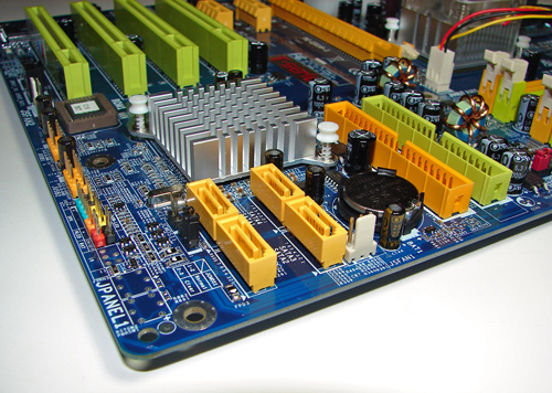
The NVIDIA nForce4 SATA ports are conveniently located below the MCP chipset and to the left of the IDE connectors. The SATA ports feature the new clamp and latch design. Unlike other recently reviewed boards, the SATA ports are not color-coded for primary and secondary operation. We found the positioning of the SATA ports to be excellent when utilizing the PCI slots or IDE port connectors.
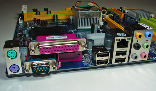
The NVIDIA nForce4 USB connectors, S/PDIF out connector, and chassis panel are located to the left of the MCP chipset along the edge of the board. The BIOS chip is located below the fourth PCI slot. The clear CMOS jumper block is a traditional jumper design located below the number one SATA port connector. The location of this jumper required the removal of the SATA drive cable during repeated usage.
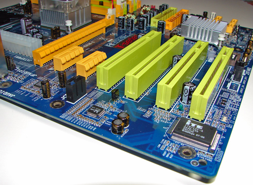
The physical x16 connector is located next to the 24-pin ATX power connector. The (2) PCI Express x1 connectors are located next, followed by the (4) PCI slots.
We did not have any issues installing our EVGA 7800GTX 512MB or ATI X1900XTX video cards in the x16 PCI Express slot. This configuration will physically render the first PCI Express x1 slot useless. We did not have any issues utilizing this slot with video cards containing single slot cooling systems.
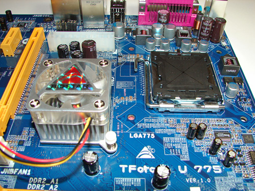
The NVIDIA nForce4 SPP chipset is actively cooled with a large heat sink/fan unit that did not interfere with any installed peripherals. In fact, this unit kept the normally hot SPP chipset cool enough that additional chipset voltage was not a factor in our overclocking tests. Our only concern is the lifespan of the fan as it typically runs at 5500rpm and does generate a slight whirling sound during operation.
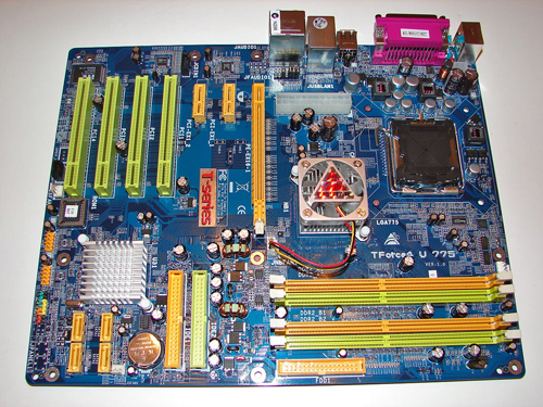
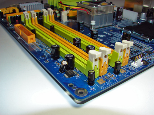
Biostar places the four-pin 12v auxiliary power connector at the top of the CPU socket area, but out of the way of aftermarket cooling solutions. The 24-pin ATX power connector is located above the SPP chipset and next to the x16 PCI Express connector. This 24-pin connector is located in a difficult position and can hamper airflow with cabling that crosses over the SPP heatsink/fan or directly over the CPU heatsink/fan.
The NVIDIA nForce4 SATA ports are conveniently located below the MCP chipset and to the left of the IDE connectors. The SATA ports feature the new clamp and latch design. Unlike other recently reviewed boards, the SATA ports are not color-coded for primary and secondary operation. We found the positioning of the SATA ports to be excellent when utilizing the PCI slots or IDE port connectors.
The NVIDIA nForce4 USB connectors, S/PDIF out connector, and chassis panel are located to the left of the MCP chipset along the edge of the board. The BIOS chip is located below the fourth PCI slot. The clear CMOS jumper block is a traditional jumper design located below the number one SATA port connector. The location of this jumper required the removal of the SATA drive cable during repeated usage.
The physical x16 connector is located next to the 24-pin ATX power connector. The (2) PCI Express x1 connectors are located next, followed by the (4) PCI slots.
We did not have any issues installing our EVGA 7800GTX 512MB or ATI X1900XTX video cards in the x16 PCI Express slot. This configuration will physically render the first PCI Express x1 slot useless. We did not have any issues utilizing this slot with video cards containing single slot cooling systems.
The NVIDIA nForce4 SPP chipset is actively cooled with a large heat sink/fan unit that did not interfere with any installed peripherals. In fact, this unit kept the normally hot SPP chipset cool enough that additional chipset voltage was not a factor in our overclocking tests. Our only concern is the lifespan of the fan as it typically runs at 5500rpm and does generate a slight whirling sound during operation.
Biostar places the four-pin 12v auxiliary power connector at the top of the CPU socket area, but out of the way of aftermarket cooling solutions. The 24-pin ATX power connector is located above the SPP chipset and next to the x16 PCI Express connector. This 24-pin connector is located in a difficult position and can hamper airflow with cabling that crosses over the SPP heatsink/fan or directly over the CPU heatsink/fan.


31 Comments
View All Comments
Ecmaster76 - Thursday, February 16, 2006 - link
If they do they might acually catch up with AMD.Supposedly their CSI project is falling apart. If they swallow their pride their server department would find a boon in HT